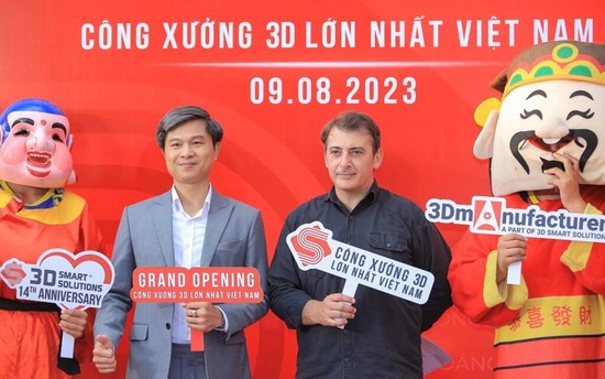
After nearly one year of construction, installation and acceptance according to international standards, the 3D factory of 3D Smart Solutions Company (also known as 3DS) has been put into operation at address 58/6 Vo Van Hat, Long Truong Ward, Thu Duc City (aka District 9), Ho Chi Minh City.

3D Scan And CAD Comparisons Of Large Castings
The MetraSCAN 3D scanner supports many processes in the production of large foundry patterns made of wood, plastic block materials, and foam.

3D Scanning Resolves Quality vs Cycle Time Conundrum
Scanning probe technology is set to have an even more dramatic effect on the industry. Article by Renishaw.
Take a trip back in time, just a quarter of a century ago, and we’d find the automotive sector taking its first tentative steps into on-machine probing. Migration to touch-trigger probe technology went on to have a profound effect on manufacturing efficiency and productivity. Today, scanning probe technology is set to have an even more dramatic effect on the industry.
From Touching to Scanning
Traditionally speaking, touch-trigger probes have predominantly been used for part set-up. While typically only gathering a limited number of data points, they nevertheless made part setting 10 times faster than previous manual methods. Early adopters were quick to realise the advantages of collecting more data to further enhance production processes.
Gathering more data from on-machine probing quickly led to the concept of automated in-process measurement, to help control part-to-part variation. It also enabled the verification of critical features—position, diameters etc. —helping to reduce offline inspection bottlenecks.
Enter 3D scanning probe technology. For automotive manufacturers, whether they be producing combustion engine, hybrid or electric vehicles, it means new capabilities in the accurate and efficient measurement and inspection of complex forms or features—with minimal impact on machine cycle times.
Comparing Technologies
The basic structure of both touch-trigger and 3D scanning probes is compared in Figure 1, respectively, illustrating Renishaw’s OMP60 and OSP60 analogue machine tool probes.
The former incorporates a spring-loaded kinematic mounting of rods and balls to hold the stylus mount. As the push-force on the stylus increases, so does the resistance measured through the kinematics’ circuit. A trigger threshold is reached and trigger signal generated.
The 3D scanning probe is built on Renishaw’s SPRINT technology. In this case, two concentric rings are employed, one fixed to the probe body, the other to the stylus mount. Continuous capacitance measurements between the ring circuits enable the position of the moving stylus tip to be accurately recorded at all times.
More Data. More Speed.
In short, depending on the number of touch-trigger points taken and the machine in question, scanning can be up to ten times faster than touch-trigger. To better quantify its data gathering and speed advantage though, consider its use in a real rough-surface application.
To continue reading this article, head on over to our Ebook!
Check these articles out:
Renishaw: SFP2 Surface Finish Measurement Probe
Multisensor Measurement: Into A New Era
Teradyne Appoints New President Of Universal Robots
Creaform To Showcase 3D Scanning Innovations For Metalworking Industry At EMO Hannover 2019
Hexagon Touch Probe Transforms Thickness Measurement on Machine Tools
Sandvik Coromant Announces Metal-Cutting Collaboration With Autodesk Fusion 360
For other exclusive articles, visit www.equipment-news.com.
WANT MORE INSIDER NEWS? SUBSCRIBE TO OUR DIGITAL MAGAZINE NOW!
FOLLOW US ON: LinkedIn, Facebook, Twitter

Creaform Releases the SILVER series HandySCAN 3D
Creaform has announced the latest addition to its HandySCAN 3D line-up offer, the SILVER series.
Developed and manufactured in North America, the SILVER Series captures highly accurate and repeatable 3D measurements of any complex surface in any location. It represents the best value for money on the market and is supported by a global team of engineers and technicians.
The SILVER series offers a versatile professional 3D scanner, with all the features that made the HandySCAN 3D scanners the reference in the industry:
- Quality optics: Provides reliable and maximised scan quality with an accuracy of up to 0.030 mm (0.0015 in).
- 7 lasers crosses: Can quickly capture the surfaces in the entire field of view with a scan area of 275 x 250 mm (10.8 x 9.8 in).
- Versatility: One device for all shapes and sizes, it masters various objects regardless of the part size, complexity, material, or color.
- Plug and play: A simple user interface and real-time visualisation offers an ease of use and a short learning curve, regardless of the user’s experience or expertise level.
- On the go scanning: Portable, lightweight and quick to set up, it can be up and running in less than 2 minutes, either in-house or on site.
- Available in 2 models: Customers can choose from two models based on their business needs -HandySCAN 307 at US $19,990 or the HandySCAN 700 at US $29,900.
“For the professionals who need to adapt quickly to their customers’ needs and provide better answers to their inquiries, a reliable 3D scanning solution is indispensable,” explains Simon Côté, Product Manager at Creaform.
“The possibilities presented by gathering such precise data can open doors to new projects and strengthen the partnerships with existing clients. It cannot be overstated how 3D scanning and 3D printing technologies have become vital for any small-to-medium sized company.”
Check these articles out:
3D Scanner Market To Experience Double Digit Growth Till 2022
Farsound Achieves Aviation Suppliers Association’s Quality System ‘ASA-100’ Certification
Winning, In More Ways Than One
Metrology-Grade 3D Measurements Right on the Production Floor
For other exclusive articles, visit www.equipment-news.com.
WANT MORE INSIDER NEWS? SUBSCRIBE TO OUR DIGITAL MAGAZINE NOW!
FOLLOW US ON: LinkedIn, Facebook, Twitter

From Users for Users
Here’s how one company was able to scan large and very heavy parts from all four sides and from above, without having to laboriously move the piece. Article by ZEISS.
When a robot grasps a cylinder block weighing 50 kilos and approaches a saw or milling cutter, any vibration or sliding motion must be avoided. But deviations from target production data make it difficult for the robots to grasp. August Mössner GmbH & Co. KG, which manufactures specialised machinery for the foundry and aluminium industries along with saws for the widest possible variety of materials as well as equipment for the dismantling of nuclear power stations, has found a solution for this problem. As well as tailor-made manipulators for robots manufactured with the aid of the ZEISS T SCAN, the programming of the equipment is optimised with flexible laser scanning.

Christian Kunz (right) and Christian Haase inspect the grippers of a robot. They are to hold heavy motor castings to the processing stations later on, which protrude from the wall on the right.
The two robot arms rigidly stretch their necks into the air, their movements appear frozen. One of them holds a cylinder block in suspension, weighing at least 50 kilos. Only in a few weeks’ time, when the entire plant has been completed, will they start moving and saw off disturbing feeder and sprue systems and mill off casting flashes on engine blocks coming from a foundry. To do this, they heave the parts to saws and milling machines that protrude from the wall and look like giant dentist drills.
Here at August Mössner in Eschach is not where they will be put to work, however, but rather at engine plants of well-known automobile manufacturers. The processing stations are designed and put into trial operation at August Mössner, which has a reputation in the automotive industry for delivering automated production lines with dozens of robots on schedule and perfectly functional.
Deviations of Several Millimetres
Christian Kunz is the Head of Robotics, R&D, at August Mössner. His team plays an important role when it comes to deviations. The 20 employees of his robotics, research and development department are responsible for planning the precise, safe and efficient operation of the processing lines.
But the devil is in the details. One of these details are the contour parts with which the robots grip the cylinder block. They are as small as a hockey puck, but must be able to grip the casting precisely and hold it in position during processing, against the forces that occur. For this purpose, the contour parts have recesses that fit exactly over the bulges of the castings. However, this is initially not the case.
Kunz holds a contour part to the rough casting of a gearbox-housing, at the point where the robot is later to pick up the component. But no matter how the mechatronic engineer turns and tilts the fitting, the parts do not fit together. “When car manufacturers send us castings, they often deviate from the target design by a few millimetres,” explains Kunz.
This is no wonder, since most of them are so-called start-up parts for new engine types.
The tolerances are still large when series production starts and are not shown in the CAD models of the castings. Kunz and his team have found a solution in which ZEISS T-SCAN is of central importance. Using a hand-held laser scanner, the engineers measure the surface contour of the casting—for example, of an engine block or a transmission housing—and compare the data set generated by this with the target CAD data supplied by the car manufacturer. On the one hand, this serves to document the actual state and on the other hand, the measurement is the basis for adapting the contour parts to the casting and for subsequent programming of the robot. In this way, the engineers can quickly see where there are deviations and can immediately initiate reworking of the contour parts. The contour part is reworked by hand, then scanned and can thus be documented and converted into CAD data.
To continue reading this article, head on over to our Ebook!
For other exclusive articles, visit www.equipment-news.com.
Check these articles out:
The Global Aluminium Castings Market To Grow By US$32.1 Million Despite The Pandemic
Sandvik Coromant Joins Forces With Microsoft To Shape The Future Of Manufacturing
Round-the-Clock Environment Disinfection With SESTO Autonomous Mobile Disinfectant Robot
5G Integration In IIoT Systems Accelerates Industry 4.0 In The Wake Of Pandemic
Six Factors That Have Changed Bending Automation
Automation Trends in Metalworking
3D Technologies: Not Out Of Our League
WANT MORE INSIDER NEWS? SUBSCRIBE TO OUR DIGITAL MAGAZINE NOW!
FOLLOW US ON: LinkedIn, Facebook, Twitter

Metrology-Grade 3D Measurements Right on the Production Floor
In this article, Guillaume Bull discusses the insights that led to the development of Creaform’s latest optical CMM scanner.

Operator scanning an industrial mold directly on the shop floor.
Over the last few years, manufacturing companies have seen their time to market expedited due to intensified competition on the global scale. In addition, the parts and assemblies that they produce are now more complex than ever.
On the one hand, they face pressure to accelerate their workflows. On the other hand, they must meet quality standards that are constantly rising. Creaform is fully aware that today’s manufacturers are facing tremendous challenges. They know that product quality issues impact scrap rate, production ramp-up, production rate, and downtime, ultimately affecting production costs and overall profitability. Consequently, Creaform’s product development team started on their task, with their clients’ issues and needs in mind.
The objective was to develop the ideal 3D scanner that could be integrated seamlessly into any quality control (QC), quality assurance (QA), first article inspection (FAI), maintenance, repair and operation (MRO), or reverse engineering workflow, and operated by users of any skill level in any type of environment—including the production floor.
Creaform wanted to offer production and quality professionals an alternative solution to the coordinate measuring machine (CMM), where parts are usually brought for FAI and QC. By doing so, non-critical inspections could be relocated and even performed right on the production floor to offload the CMM and keep it available for inspection of crucial dimensions. Creaform also wanted to develop a tool more suited for QA, since quality issues can come from multiple parts, all with different sizes, shapes, and surface finishes. Creaform’s engineers had definitely a lot on their plate.
Faster, More Accurate, and More Versatile Portable 3D Scanner
Creaform’s engineers kept these objectives and challenges in mind when they developed the MetraSCAN BLACK. They were determined to take dimensional measurement speed, accuracy, and versatility to a whole new level.
Speed
Now featuring 15 blue laser crosses, which can take up to 1,800,000 measurements per second, the new metrology-grade 3D scanner offers a larger scanning area and accelerated scanning time. Such a measurement speed—4X faster than the previous version—ensures an optimized acquisition time and data processing rate in order to provide users with instant meshing. In short, the measurement workflow from setup to real-time scans and ready-to-use files has never been faster.
To continue reading this article, head on over to our Ebook!
For other exclusive articles, visit www.equipment-news.com.
Check these articles out:
How to Quickly, Easily and Automatically Measure Radii and Defects
Six Key Considerations When Selecting A Gantry CMM
HEIDENHAIN Presents Controls And Measuring Technology For Efficient Production
Samsung Working To Develop Its Vietnamese Supply Chain Networks
API’s Improved vProbe For Enhanced CMM Measurements Directly On Production Floor
Large-Scale Metrology For Oil Industry Production
Sheet Metal Fabricator Cuts Inspection Time by 60%
Unlock The Hidden Potential Of Your CMMs
The Importance of Automation for Networked Manufacturing and Digitisation
WANT MORE INSIDER NEWS? SUBSCRIBE TO OUR DIGITAL MAGAZINE NOW!
FOLLOW US ON: LinkedIn, Facebook, Twitter

Creaform Releases Optical CMM Scanner MetraSCAN BLACK
Creaform has released its latest version of the MetraSCAN 3D lineup, the company’s advanced optical CMM scanner designed specifically to perform metrology-grade 3D measurements and inspections. As the fastest and most accurate portable optical CMM scanner, the MetraSCAN BLACK can be seamlessly integrated in any quality control, quality assurance, inspection, MRO, or reverse engineering workflow and operated by users of any skill level in any type of environment.
The MetraSCAN BLACK dimensional metrology system has been developed to measure complex parts and assemblies from an array of industries and manufacturing processes, such as automobile, aeronautics, power generation, heavy industry, metal casting, metal forging, sheet metal, plastic injection, composites, etc.
Featuring unmatched performance and speed for optimized 3D measurements
- 4X faster: Featuring 15 blue laser crosses for larger scanning area that take up to 1,800,000 measurements per second and live meshing, ultimately cutting down the time between acquisition and workable files.
- 4X resolution: MetraSCAN BLACK features a measurement resolution of 0.025 mm (0.0009 in) to generate highly detailed scans of any object.
- More accurate and traceable measurements: High accuracy of 0.025mm, based on VDI/VDE 2634 part 3 standard and tested in a ISO 17025 accredited laboratory, ensures complete reliability and full traceability to international standards.
- Shop floor accuracy: The MetraSCAN BLACK features a unique and patented dynamic referencing that compensates for surroundings instabilities.
- Maximum versatility: Masters complex, shiny and highly detailed parts
- No warm-up time: Operators can be up-and-running in minutes.
- Touch probing capability: When paired with the HandyPROBE, the MetraSCAN BLACK lets users harness the power of both 3D scanning and probing for a complete, streamlined inspection process.
- Available in BLACK and BLACK|Elite: Customers can choose from two models based on their needs: speed, part complexity, accuracy, etc.
“Today’s manufacturers are facing tremendous challenges. They are under increased pressure to accelerate their time to market in order to remain competitive on the global scale. Product quality issues impact scrap rate, production ramp-up, production rate, and downtime, ultimately affecting production costs and overall profitability. Manufacturers need to rely on innovative 3D measurement technologies, like the MetraSCAN 3D, in order to refine their product development and quality control processes,” explained Guillaume Bull, Product Manager at Creaform.
“This new version of the MetraSCAN 3D takes dimensional measurement speed, accuracy and versatility to a whole new level. We believe manufacturers will appreciate its performance within their workflows.”
For other exclusive articles, visit www.equipment-news.com.
Check these articles out:
Raising Productivity with Plasma Systems
NUM Launches Form Compensation Option For NUMROTO Tool Grinding Software
Innovating Shopfloor Inspection: A Look At The Next Generation CMM
Hexagon’s Absolute Arm Now Features 3D Laser Scanner
Creaform To Showcase 3D Scanning Innovations For Metalworking Industry At EMO Hannover 2019
Hexagon Enhances Portfolio For CMM With Swift-Fix Chucks
6 Points To Better CMM Maintenance
WANT MORE INSIDER NEWS? SUBSCRIBE TO OUR DIGITAL MAGAZINE NOW!
FOLLOW US ON: LinkedIn, Facebook, Twitter

3D Scanning Prevents Production Downtimes
Digitalisation and measurement made it possible to modify mould inserts and allow them to be exchanged, thus avoiding downtime for this manufacturer. Article by GOM.

Triple Scan Principle. (Image source: Lometec)
In the past, measurement service provider Lometec had ‘merely’ conducted some workpiece first-sampling for one of its customers, a well-known medium-sized plastics processor. But when an urgently needed, brand-new tool suddenly failed, the metrologists moved out on a special mission: Delivering overnight service, they digitalised the mould tools using GOM scanning systems so that precise, rapid reworking was possible. The impending default on delivery was averted.
Lometec’s customer produces, among other things, thermoplastic weather-proof housings designed for use in extreme climates. When the quantities in demand began exceeding the existing tool’s capacities, the company commissioned construction of a second, identical tool—and that’s where the trouble began.
Tool Failure After Passing First Sampling
At first, everything was looking hunky-dory: The new tool was delivered and worked just fine, as verified by Lometec as part of first sampling of the housing. The 3D measurement service sampled 125 parts and recorded the results in the initial sample test report (ISTR). Process capability was validated and the plastics processor was able to produce with two tools at once, doubling output as desired.
But shortly after starting mass production with the second tool, it proved prone to faults: Sliders and inserts began seizing. The tool manufacturer responded promptly to the complaints and supplied spare parts—but these did not match precisely, making it impossible to simply exchange them, never mind swapping over the sliders and inserts between the two tools.
The Solution: Scan and Rework—ASAP
This gave the plastics processor the idea to have Lometec digitalise and measure the 14 affected mould inserts and sliders. The measuring data would then be used to rework the imprecise spare parts.
Lometec Managing Director Jörg Werkmeister remembers, “Our job was to compare the old inserts with the new ones and return all of the inserts to the company again as quickly as possible, so they’d be able to keep on producing with one tool at least. Having both tools measured was naturally stopping production completely.”
No sooner said than done: being specialists for rapid optical 3D measurement, Lometec was confident they had what it took. The measurement service maintains two fully climatised measuring rooms and uses measuring equipment by renowned German manufacturers, including three GOM systems for full-field digitalisation of technical mould halves.
“We set up the 3D scanning lab completely from scratch in 2016, it’s absolutely state-of-the-art,” Werkmeister says. “Our trio of ATOS Triple Scan, ATOS Core and ATOS ScanPort means we’re excellently equipped for a diverse range of digitalisation jobs.”
Investing in GOM technology had been very good decision, Werkmeister goes on to say. “The measuring data the systems supply are outstanding.”
To meet the demand for promptness, two metrologists tackled the plastics processor’s job in tandem: one working with ATOS Triple Scan, the other with ATOS Core.
Before conducting the measurements, the metrologists cleaned the sliders and inserts, removing residues such as grease and the like. Next, they applied high-precision reference point markers. These ensure that the software joins the separate scanned images correctly.
“For digitalisation, we chose really small increments,” says Werkmeister. This achieved high detail resolution.
To continue reading this article, head on over to our Ebook!
For other exclusive articles, visit www.equipment-news.com.
Check these articles out:
Are Cheaper CNC Machine Tools More Cost Effective?
Complete Measurement Solution for Consistent Quality Management
No Longer Pressed For Time With Portable Measuring Devices
A Look At How 3D Measurement Technology Helps Reduces Total Lead Time
Hexagon Enhances Portfolio For CMM With Swift-Fix Chucks
Faro: Factory Robo-Imager Mobile
Hexagon: Time-Saving And Productivity Enhancements In Latest VISI
WANT MORE INSIDER NEWS? SUBSCRIBE TO OUR DIGITAL MAGAZINE NOW!
FOLLOW US ON: LinkedIn, Facebook, Twitter

High-precision Layer Work
Find out how MBFZ toolcraft ensures holistic quality control and precision in additive manufacturing. Article by ZEISS

Frederik Mack, Materials Engineer at toolcraft, examines a test specimen under the ZEISS Axio Imager microscope, which he sawed out of a 3D-printed part and ground.
Additive manufacturing is an uncharted territory for many companies, but not for MBFZ toolcraft GmbH. The company in Georgensgmünd, Southern Germany, manufactures high-end precision parts for the aerospace, automotive, medical technology and semiconductor industries, among others, and since 2011 also parts using 3D printing. The young established production technology is a challenge for quality assurance. Toolcraft is mastering this challenge with ZEISS 3D ManuFACT, the only solution on the market for continuous quality assurance in additive manufacturing.
Heat, noise, the smell of oil: They belong to industrial manufacturing like Yin to Yang. Yet this is quite different in the glass hall at toolcraft in Georgensgmünd. Anyone who has access to the area with their employee ID card hears nothing. They smell nothing either. There are few reminders of factory life as we have known it for a hundred years, because parts are not manufactured the way they have been for a hundred years. Instead of peeling the mold out of cast or forged metal blocks by drilling, milling and turning, additive manufacturing comes at the process from the other way.
Through small windows on the twelve 3D printing machines at toolcraft, you can watch glistening laser beams dancing over a wafer-thin layer of metal powder. Where the spot of light hits, the powder melts in a flash and immediately solidifies again, followed by the next layer. Thousands of hair-thin layers are used in 3D laser melting to create „impossible“ components that could never be produced with traditional subtractive manufacturing. Whereas ten years ago only prototypes and design studies were produced by using additive manufacturing, manufacturers of aircraft turbines, racing cars or medical equipment are increasingly incorporating them directly into their series products.
Challenges for Quality Assurance
As always, when a new technology emerges in a market, there are always questions. One of them is quality assurance. Jens Heyder points to a monitor that shows two images taken with the ZEISS Axio Imager light microscope at 50x magnification. On the left you can see a section of a good component. There are no large defects visible, only small pores. The material has an even, homogeneous structure. On the right, there is a cross cut shown, in which blowholes and welding defects are present. The construction process here was not optimal, which is why errors occurred during solidification of the melt.
“Crack formation could occur under high loads,” warned Heyder, who has been working as a material engineer in toolcraft’s materials laboratory for three years. Together with his colleagues, he checks the grain size distribution of the metal powder used. They help to optimize the manufacturing process in such a way that no defects occur in the part during melting and solidification.
However, the materials laboratory is only one component in the seamless quality assurance at toolcraft. Each process step is followed by a test: when a part comes out of the printer, after heat treatment and finally after milling into the final form, before the part is sent to the customer. Not every part is inspected. Random samples are taken according to customer requirements where typical parts only undergo a final inspection. For more demanding customer requirements, such as the aviation industry, 100 percent inspection and precision is required.
But one thing is for sure: when a part is inspected, it is done on a machine with the ZEISS logo. These can be found in several places in measuring rooms and in production at the company: two microscopes (ZEISS Axio Imager and ZEISS Axio Zoom.V16), several coordinate measuring machines (two ZEISS ACCURA, one ZEISS CONTURA and one ZEISS DuraMax) as well as an optical 3D scanner. Although the latter bears the GOM logo, the company also belongs to the ZEISS family since spring 2019.
To continue reading this article, head on over to our Ebook!
For other exclusive articles, visit www.equipment-news.com.
Check these articles out:
Intelligent Machine Software For Improved Precision Machining
Hexagon And Ericsson Host Joint Webinar On The Role Of 5G In Industry 4.0
The AMable Project Promotes Flexible AM Solutions To Fight The Coronavirus
Driving the Next Industrial Revolution
NAP 2020 Drives Malaysia’s Automotive Sector
A Look At How 3D Measurement Technology Helps Reduces Total Lead Time
Driving For A Better Tomorrow Hexagon Manufacturing Intelligence
Large-Scale Metrology For Oil Industry Production
WANT MORE INSIDER NEWS? SUBSCRIBE TO OUR DIGITAL MAGAZINE NOW!
FOLLOW US ON: LinkedIn, Facebook, Twitter

The Importance of a Calibrated and Traceable Artefact
What is the most accurate way to check if a measuring tool works within its specifications? Guillaume Bull, product manager at Creaform, explains in this article.

When replacing old measuring equipment, it is common to validate that both the old device and the new device measure the same data and provide quality control (QC) with the same results. To do this, correlation tests are performed.
To facilitate and speed up the work, it is tempting to test a regularly manufactured part. After all, its specifications are well known. However, this choice of part may lead to a false diagnosis and an incorrect conclusion regarding the accuracy of the new measuring device.
Therefore, the most accurate way to check if a measuring tool works within its specifications is to use a calibrated artefact for which measurements have been previously validated and the data is traceable.
READ: Quality Assurance Brings New Confidence
Using a common artefact for the old device and the new device helps to minimize the variables that can influence the correlation tests. Among these variables, which will induce measurement differences, are the extraction methods that are different from one technology to another, the alignment methods that are rarely the same, software that does not process or calculate data in the same way, the setups that are generally different depending on the technologies, and the environment that, if not maintained exactly the same, will greatly influence the measurements.
Using a calibrated and traceable artefact enables operators to validate that both devices work within their specifications. As a result, if the measurements taken on this calibrated artefact give the right value, we will know for sure that the measuring devices work properly.
Scenario
A manufacturing company working in the automotive industry wants to replace its CMM with a 3D scanner. In order to validate the new equipment, a correlation test is performed between the two devices—the old and the new. When the two measurements are compared, there is a difference; the instruments do not correlate with each other. Why? Should we not get the same measurement on both instruments? What is causing this difference? Since we know that the old equipment has been accurate historically, should we conclude that the new equipment has an accuracy issue?
READ: Optimising Aerospace Parts Manufacturing
When testing for correlations between two types of equipment (i.e., comparing the measurements obtained on the same part with two instruments), there are many variables that can induce errors in the measurements. These variables include extraction and alignment methods, software calculation, setup, and environment.
Extraction Methods
We measure the same part, but we do not extract the same points with one measuring tool as we do with the other tool. The consequence is a difference in measurement due to the imperfection of the geometry of the part. Indeed, when we probe a surface plan by taking a point at the four corners, this method does not consider the surface defaults of the plan. Conversely, if we scan this plan, we measure the entire surface and get the flatness. Therefore, if the surface has a slight curve, the scanned plan might be misaligned compared to the probed plan. Thus, there will be a difference in measurement between the two methods.
Alignment Methods
We measure the same part, but we use two different methods of alignment. The consequence is a slight difference in the alignment method, which can lead, due to leverage, to large deviations at the other end of the part. Even if the same method of alignment is used, as mentioned above, a difference in the extraction method of the features used in the alignment can lead to a misalignment of the part. The positioning values are based on the alignment, which must not differ from one instrument to another, neither in the construction method, nor in the way it is measured.
Software Computation
We measure the same part, but we use different software that does not use the same algorithms for data processing. The consequence is a difference in the calculation of a feature from the software, even though the measured data is the same. The more complex the construction of the measurement is, the more likely it is to have deviations between calculations.
READ: A Guide to Machining Better Castings Through Optical Metrology
Setup
We measure the same part, but we do not have the same setup on both instruments. The consequence is different measurements of this same part. For example, a part of large dimensions is measured on a CMM. The marble on which the part is placed has an excellent flatness (30 microns). The same part is then measured with a 3D scanning system. But the surface on which the part is put has a different flatness (800 microns). As a result, the part twists and deforms slightly when placed on the second marble. Although the same part is measured, the two setups give different measurements because the support surfaces have different degrees of flatness.
Environment
We measure the same part but under different conditions. The consequence is a difference in the measurements. Indeed, if we measure an aluminium part of one meter on a CMM at an ambient temperature of 20 deg C and we measure the exact same part at 25 deg C, then the difference in temperature will result in a lengthening of the part by 115 microns at 25 deg C.
Common Artefact
It is crucial for quality control to minimize these different variables that could lead to correlation errors. The easiest way is to use, on both instruments, a common artefact for which measurements have been previously validated and the data is traceable.
Artefacts have the distinguishing characteristics of being calibrated and traceable. All features have been previously measured and verified in a laboratory, eliminating any doubt and uncertainty regarding measurements.
READ: Creaform Launches 3D Scanning Solution Suite for the Aerospace Industry
Conclusion
A value commonly obtained with a traditional measuring instrument is not a reference value that can be relied upon 100%. The reason for this is that equipment is not an artefact. There is always uncertainty associated with any measuring instrument. Therefore, the verification, validation, or qualification of a measuring instrument cannot be done with any part for which dimensions have not been previously validated.
The only way to certify that a measuring tool works within its specifications is to compare it with an artefact whose dimensions are calibrated in a known laboratory. Only an artefact makes it possible to correlate measurements between equipment because only an artefact can subtract all the variables that could interfere with the measurement. Thanks to an artefact, there is no doubt; the equipment measures accurately.
If two devices get the same measurement with an artefact, but do not correlate on a specific part, then the difference is not attributable to the instruments. Rather, it will result from measurement processes that will need to be checked and scrutinized further to obtain the desired measurement.
For other exclusive articles, visit www.equipment-news.com.
Check these articles out:
Tackling Shop Floor Inspection Challenges
ZEISS Completes GOM Acquisition
Hexagon Touch Probe Transforms Thickness Measurement on Machine Tools
Complete Measurement Solution for Consistent Quality Management
FARO Sees Bright Prospects in Automotive Manufacturing Industry
Speeding Up And Simplifying Solutions
Creaform Launches 3D Scanning Solution Suite for the Aerospace Industry
Ensuring That A Propeller Keeps A Heart Beating
Blum-Novotest To Highlight Measuring, Testing Technology at EMO 2019
Haimer: Microset Tool Presetters
Hexagon Intros Modular Metrology Fixtures to Online Shop
WANT MORE INSIDER NEWS? SUBSCRIBE TO OUR DIGITAL MAGAZINE NOW!
FOLLOW US ON: LinkedIn, Facebook, Twitter
- 1
- 2