skip to Main Content
How Can Portable CMMs Help Improve Machine Shop Workflow?

How Can Portable CMMs Help Improve Machine Shop Workflow?

Innovations in the compact metrology space are changing the way machine shop inspection works for the better. By Bernard Chou, regional product line manager (portable), APAC at Hexagon Manufacturing Intelligence. 

New hardware, advanced 3D measurement capabilities and integration with CAD and enterprise metrology software packages is opening a range of new opportunities for greater inspection productivity and manufacturing process optimisation.

Today’s portable device alternatives include portable measuring arms, laser trackers and scanning systems, making it convenient to move a level of quality assurance directly onto the shop floor.

Depending on the system, it’s possible to provide accurate measurements within a range of 15-100 microns. While still not yet at the level of the high-precision work done by stationary CMMs in the lab, this degree of accuracy is entirely suitable for many of the measurement tasks typically found on the shop floor.

Speed Of Production

On the shop floor, uptime is what matters most, and any tool that best maximises metal cutting time rules the day. Using portable devices for making in-process checks or first-piece inspections (if accuracy permits) can be the difference when it comes to maximising uptime, as no effort is wasted getting parts to a remote measurement location and then waiting for inspection results to come back.

The key to getting fast measurement results from a portable device at or near a machine tool is preparation. For the latest generation of arm-type instruments, this means simply knowing what features to measure, selecting them using a graphic user interface and following the prompts.

Users can even perform complex evaluations on the shop floor using portable arms equipped with the same software found on stationary CMMs. This type of software uses a CAD model to generate efficient probe paths and allows for the generation of as much as 90 percent of a measurement programme offline before even taking the portable measurement device to the part.

What’s more, if a first-piece CMM inspection programme already exists for measuring a part, users can import all or part of the programme into the portable software package with minimal changes, eliminating most of the required programming and saving time. All that needs to be done at this point is taking the portable device to the part, orienting the part to the device and performing the required measurements.

In a guided inspection routine, the user interface that uses the CAD model as a reference will show the operator where to probe the part and then immediately display the measurement results. Colour-coding (green/red) on the CAD model view of the part will indicate where it is in or out of tolerance.

This kind of instant feedback is a win-win for the manufacturing and quality departments; portable users on the shop floor obtain measurement results immediately, and they do so without tying up the CMMs in the quality laboratory, which often has a heavy workload on other tasks.

Fitting Conclusions

Even when a part on a machine has a problem, it is not always necessary to scrap it. Those familiar with CMMs already know how to use their software’s best-fit capabilities to answer a wide range of questions about a part:

  • The casting is malformed, but is there enough material available to make a good part from it anyway?
  • Is there enough material available on this bad part to re-machine it and make a good one?
  • By reorienting this rejected part in three dimensions within the measurement programme, can I match up the critical features more closely to the CAD model and avoid rejecting it?

Answering these questions and others like them presents opportunities for salvaging valuable parts with many resources and hours of work already invested in them.

Additionally, moving the answers from the quality lab to the shop floor is a sure-fire route to significant efficiency savings, whether that be from the reduced time spent assessing errant parts, or the increased number of parts repurposed by eliminating the guesswork involved in deciding which parts are worth fully assessing.

Process Problem Solving

Good manufacturing people are ingenious when it comes to devising on-the-spot solutions to dimensional problems that materialise unexpectedly. These impromptu adaptations may include the use of shims, special fixtures and ad hoc machine tool offsets, allowing the machinist to ship good parts out the door without having to double back and find the root cause of and correct every problem immediately.

Portable measurement systems are an excellent aid in making such improvisations, allowing experienced machinists to work faster and with greater accuracy as they correct mistakes on the fly.

And once the immediate problem is solved, the portable measurement system becomes a vital tool in tracing the out-of-spec condition back through the various manufacturing operations to identify and fix the root cause of the problem. The operator will be able to follow this problem-solving process using defined measurement knowledge rather than guesswork, ultimately accelerating the entire process of unwinding the problem.

From Basic To Advanced

Usability is always important for portable measuring devices, and while easy to understand and use, they actually support a broad range of user capabilities.

For novice operators, a simple, intuitive user interface is presented for checking basic characteristics of parts or using pre-programmed measurement routines written by CMM experts to check more complicated geometry. This makes it a quick and easy process for operators to learn to perform in-process checks or do pass/fail inspections of their own parts.

Users at the more sophisticated end of the scale most likely have a working knowledge of CAD and CAM. They will have little trouble using advanced portable devices and software to expedite setups or troubleshoot manufacturing process problems.

And quality assurance staff will be able to deploy portable measurement approaches to get measurement results faster and closer to the process while eliminating bottlenecks at the CMM in the laboratory, allowing product development work to avoid continuous interruptions for the sake of keeping manufacturing on schedule.

This flexibility in allowing users at different levels to handle tasks of varying complexity with the same tools has obvious benefits. In terms of cost-effectiveness, purchasing and training on a single tool present a clear opportunity to avoid unnecessary spending.

The Road To Efficiency Is Portable

The field of industrial metrology has now reached the point where portable devices with CAD-based measurement software are no longer speciality items, but mainstream tools that can be used to detect the causes of dimensional problems when and where they occur.

By measuring at or near the machine, measurement-related time-wasters can be minimised and measurement backlogs at stationary CMM sites can be cut significantly, both of which are key factors in improving new programme delivery cycles.

CHECK OUT THESE OTHER ARTICLES

Real-Time Shop Floor Integration, Simplified
Tackling Shop Floor Inspection Challenges
Hexagon Launches PC-DMIS 2019 R2
A New World of Laser Tracker Scanning
Wenzel: Towards a Closed Loop Measurement Environment
New High-Definition Feature Scanner For Automated Inspection
Hwacheon on VMCs vs. HMCs
Achieving Perfect Gaps And Joints
Walter: Tool Life App
ASEAN Region In Focus Of German Machine Tool Industry

WANT MORE INSIDER NEWS? SUBSCRIBE TO OUR DIGITAL MAGAZINE NOW!

FOLLOW US ON: LinkedIn, Facebook, Twitter


Rock Solid Foundations: Granite For High Accuracy Measurement

Rock Solid Foundations: Granite For High Accuracy Measurement

With its durability and vibration dampening properties, granite is the ideal material for all components of industrial metrology. By CP Chuah, general manager, commercial operations Asia Pacific, Wenzel Asia 

The use of granite in 3D coordinate metrology has already proven itself for many years. No other material fits with its natural properties as well as granite to the requirements of metrology.

The requirements of measuring systems regarding temperature stability and durability are high. They have to be used in a production-related environment and be robust. Long-term downtimes caused by maintenance and repair would significantly impair production.

For many years now, manufacturers of coordinate measuring machines trust in the quality of granite. It is the ideal material for all components of industrial metrology which demand high precision.

Granite’s Favourable Characteristics

The following properties demonstrate the advantages of granite:

  • High long-term stability: Thanks to the development process which lasts many thousand years, granite is free of internal material tensions and thus extremely durable.
  • High temperature stability: Granite has a low thermal expansion coefficient. This describes the thermal expansion at the temperature changing and is only half that of steel and only a quarter of aluminium.
  • Good damping properties: Granite has optimal damping properties and thus can keep vibrations to a minimum.
  • Wear-free: Granite can be prepared so that a nearly level, pore-free surface arises. This is the perfect base for air bearing guides and a technology which guarantees the wear-free operation of the measuring system.

Manual Labour As Predicate

Based on the favourable characteristics above, the base plate, rails, beams and sleeve of Wenzel measuring machines are also made of granite. And because they are made of the same material, a homogeneous thermal behaviour is provided.

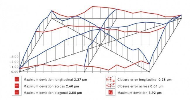
In order for the qualities of granite to apply fully when operating a coordinate measuring machine, precision is imperative when processing of the granite components are carried out. The final processing step is the hand lapping of the granite. The evenness of the lapped granite is inspected minutely with a digital inclinometer.

The flatness of the surface can be determined sub-µm-precisely and be displayed as a tilt model graphic. Only when the defined limit values are followed and the smooth, wear-free operation can be guaranteed, the granite component can be installed.

Robust Measuring Systems

In today’s production processes the measuring objects have to be brought as fast and uncomplicated as possible to the measuring systems, irrespective of whether the measuring object is a large and heavy component or a small part.

It is therefore of great importance that the measuring machine can be installed close to production. The usage of granite components supports this installation site as its uniform thermal behaviour shows clear benefits to the use of moulding, steel and aluminium.

A one metre long aluminium component expands by 23 µm when temperature changes by 1 deg C. A granite component with the same mass however expands itself for only six µm. For additional safety in the operational process, bellow covers protect machine components from oil and dust.

Precision And Durability

Reliability is a decisive criterion for metrological systems. The usage of granite in the machine construction guarantees that the measuring system is stable and precise in the long term.

As granite is a material which has to grow for thousands of years, it does not have any internal tensions and thus the long term stability of the machine base and its geometry can be ensured.

With granite being the foundation for high accuracy measurement, Wenzel purchased a granite processing business in Germany in 2006.

Granite Processing Plant

In 1885 in the German village of Groß-Bieberau, a stone cutter began a business making tools, utensils, and decorative pieces from the stone of local quarries. He likely never imagined that 130 years later his family would still be cutting stone on the same spot, though for drastically different purposes.

Run by the same family since 1885, Wenzel Steintechnik stands on the same ground today, making the granite bases and components for CMMs.

A division of Wenzel since 2006, Steintechnik evolved over the years from simple hand carved items, to designing and fabricating tombstones, evolving to the production of granite for industrial applications. The division is responsible for bringing the raw material in from the quarry, and processing it to rough size for the factory.

Work begins typically with a 35-ton block of raw material which is sawn into workable sizes for either machine tables, or components such as X-beams. These smaller blocks are then moved to other machines for finishing to their final sizes.

Reducing Processing Time

A new 5-axis vertical mill was recently purchased to streamline the manufacturing process, and reduce the handling of the stone. This gantry mill allows combining cutting, grinding, and milling operations into one, while also improving the cycle time of the processes themselves, which led to a 60 percent reduction in overall processing time.

With a working volume that can handle up to six large machine bases, the facility now has the capability for lights out production of granite 24 hours a day, seven days a week.

Improvements like these allow reduced delivery times to the end customer, and also increase the flexibility of their production schedule to react faster to changing demands.

Traceability In Granite

Another more subtle change in the manufacturing process happened some years ago, when the Steintechnik team began serialising all the components they manufacture. This allows traceability from the time a block of raw granite leaves the quarry, until the pieces are assembled into a CMM.

Should problems arise with a certain component, all other components which could be affected can be easily contained and verified for their quality, ensuring that no quality defects escape the facility.

While a commonly seen in high volume production like automotive and aerospace sectors, this traceability is new in granite manufacturing. 

Granite inspection is carried out with a digital inclinometer

Granite inspection is carried out with a digital inclinometer.

Surface flatness can be determined sub-µm-precisely and be displayed as a tilt model graphic.

Surface flatness can be determined sub-µm-precisely and be displayed as a tilt model graphic.

CHECK OUT THESE OTHER ARTICLES

Hoffman Group: Garant Disc Brushes
Big Presence For Taiwan At EMO 2019
GEFERTEC At EMO: New-Generation Machines And Applications For 3D Metal Printing
Perfect Combination – New Hybrid Laser Measuring System
KASTO Enable Meticulous Sawing Of Additively-manufactured Components
Hexagon Launches QUINDOS 2019.2
Hexagon Releases Complete Solution For Laser Scanning On The Machine Tool
Siemens Invests In New Materials Solutions Facility
Metal Powder Market Forecast To Grow At 3% CAGR Over 2018 to 2028
igus Coating Technology Makes Abrasion-Resistant Metal Components

WANT MORE INSIDER NEWS? SUBSCRIBE TO OUR DIGITAL MAGAZINE NOW!

FOLLOW US ON: LinkedIn, Facebook, Twitter

The Shape Of Scanning

The Shape Of Scanning

The rise of scanning technology is changing the landscape of quality assurance in the metalworking industry. Just what is it that makes scanning such a revolutionary measurement technology? By Mark D’Urso, product manager, marketing, Hexagon 

Non-contact scanning for measurement and analysis is growing in importance every year right across the world of materials fabrication, finding exciting new applications across a widening range of industries and settings.

In many places, scanning can be the route to massively increased speed and efficiency while delivering a new type of data to solve problems that are beyond the reach of traditional touch-probing methods.

Look, Don’t Touch

The most superficially obvious advantage of scanning over touch-probe measurement is the ability to take accurate measurements without physically touching the part being measured. The range of industries manufacturing products that require quality assurance processes applied to materials with a delicate or easily damageable finish is wide, and for such applications scanning offers a non-contact solution that traditional touch-probe CMMs cannot match.

And it is not just the point of measurement where scanners present a non-contact benefit. Readying a part to be scanned needs only a stable platform, with no clamping required, ensuring measurement accuracy. And while in the past applications for scanning were limited by the need for target markers placed on the product to be measured, the technology has by now progressed sufficiently that extremely accurate measurement results can be collected with no need to touch the component at all outside of initial placement and reorientation.

High-Speed Measurement

Such reduced preparation requirements for successful scanning introduce what is perhaps the key benefit of scanning over probing: vastly reduced measurement process times.

Scanners have the capacity to capture huge amounts of data very quickly. The exact speed at which a scanner can collect data varies with the exact type of scanning technology used, but compared with one-point-at-a-time touch-probe measurement, the point-cloud data collection of even the most basic scanner is on another level.

Even entry-level scanning solutions can capture up to 50,000 data points every second, while with the very latest laser scanning technology, that number rises to three quarters of a million.

What this comes down to is the potential for increased speed and efficiency in data collection. Every important data point needed to accurately map, for instance, a car door panel, can be collected in less than two minutes with the right scanning technology. Performing the same measurement process only 10 years ago would have presented a long task, requiring not only more measurement time but also a significant amount of preparation time in order to ensure all the most important measurement points were taken.

Even then, the data collected by touch probe would be a level of abstraction away from a proper representation of the part in question. Scanning on the other hand is able to produce a picture of a component, cataloguing every undulation and deviation in form.

A Different Type Of Data

That brings us to the other clear improvement that scanners deliver. The huge amount of data they have the capacity to collect has deeper implications than merely the ability to record the same old measurements at a faster rate. This quantitative increase in data actually translates to a qualitative difference as we move from a predefined set of key data points to a multi-million-point data cloud, representing a fundamental change in the way that data can be used.

The result is the potential to almost instantly create a three-dimensional model of the object or surface being scanned. This allows for geometric and dimensional part analysis that would be all but impossible to replicate through touch-probe measurement. With scanning technology, we can create two-dimensional cross section mappings and perform flush and gap inspections based on a range of useful geometrical definitions.

Going even further, high-volume scanning data can be used as a reverse engineering tool, useful from competitor product analysis through to the manufacture of spare parts for which no model exists, such as old aircraft components. Such functionality also allows for the update and re-design of existing CAD models based on real world production data—it is even possible to compare to CAD models in real-time with some technologies. Some scanners are even able to record accurate colour mapping that is ideal for reporting and documentation purposes.

New Applications

The range of applications to which scanning technologies are well suited is extensive, from inspecting panels during installation processes to in-depth defect analysis of composite parts. With an accurate three-dimensional model and appropriate software solution, it is now even possible to carry out virtual assembly of prototype parts for the purposes of accurate interference analysis.

Accurate surface models and cross sections are extremely useful in the aerospace and wind power industries, where improving the efficiency of turbine blades is highly important. Portable scanners also offer an interesting solution for preventative maintenance of casting dies; a quick shop-floor “health check” with a scanner can avoid costly scrapping unless absolutely necessary.

With scanning being so easily applicable within portable measurement solutions, its benefits are not limited to controlled quality room environments. Scan data can easily be collected on the shop-floor, in-line within fabrication processes or even from within a mid-installation aircraft fuselage.

Which Technology?

Portable scanning technology currently comes in several ‘flavours’, each with its own benefits and points of interest. Laser line scanning offers accurate and reliable data acquisition at high-speed across almost any surface type. This technology can be used in conjunction with a laser tracker to perform scanning tasks over large areas, and the lack of moving parts makes such laser tracker and scanner combination systems perfect for robot mounting for in-line measurement tasks.

Alternatively, laser line scanners can be found mounted on portable measuring arms for extremely fast and accurate measurement of smaller parts and surfaces, with the arm acting as a global reference system for the scanner system.

A variation on this technology is “flying dot” laser scanning, which is flexible enough to scan across multiple surface colours and materials with no settings adjustments. It is also unaffected by ambient light and offers adjustable laser line width and scan point density settings along with a larger stand-off for easier measurement.

The other major portable scanning technology comes in the form of structured light scanners, such as white light fringe projection and photogrammetry systems that offer extremely high accuracy and point-cloud resolution for small-volume measurement. While the required target markers can be slightly time consuming to position, they allow for better lines of sight by repositioning the scanner without restarting the measurement process.

With a combined fringe projection and photogrammetry system, it is now even possible to visualise the results of a measurement directly on the object being measured, offering a visceral real-world representation of your data.

The Future Of Metrology?

There are some factors that balance all these benefits when it comes to comparing scanning with traditional touch-probe measurement techniques. Perhaps the most important one is that the trade-off for increased speed and size of data collection when it comes to scanning is in terms of accuracy. This is the area in which the conventional touch-probe based CMM still wins the argument. If accuracy down to fractions of a micron is central to your measurement needs, scanning technology is not yet ready for you.

The other key argument against implementing scanning technology yesterday comes down to cost. New scanning technologies are unsurprisingly more expensive than probing solutions when controlling for equivalent levels of accuracy. As always when adopting new tools, a key part of the investment decision comes down to value, and while the benefits of scanning solutions represent a bargain for many users, for others the investment is too much—for now at least.

But for the wide range of applications that do not require data at such high accuracy levels and for which the requisite investment is justified, the benefits of scanning are absolutely clear: Scanning is the metrology technology of tomorrow.

High-volume scanning data can be used as a reverse engineering tool

High-volume scanning data can be used as a reverse engineering tool

From inspecting panels during installation processes to in-depth defect analysis of composite parts, scanners can be used for many purposes

From inspecting panels during installation processes to in-depth defect analysis of composite parts, scanners can be used for many purposes

CHECK OUT THESE OTHER ARTICLES

A Look At How 3D Measurement Technology Helps Reduces Total Lead Time
Interference For Optimal Accuracy
Hexagon Launches QUINDOS 2019.2
Record Number Of Enterprises Becoming “Intelligent” With Growing IoT Investments
Case Study: Collaboration Between Hartford And Renishaw In The Implementation Of Smart Factory Solutions
Hexagon Releases Complete Solution For Laser Scanning On The Machine Tool
3D Goes Long-Range With The First Scanning Laser Tracker
Hypertherm Releases Major Version Update Of Robotmaster Robot Programming Software
Gehring Laser Technology Helps VW Develop High-Efficiency Engine
Wenzel To Showcase Metrology Innovations at EMO 2019

WANT MORE INSIDER NEWS? SUBSCRIBE TO OUR DIGITAL MAGAZINE NOW!

FOLLOW US ON: LinkedIn, Facebook, Twitter


Driving Innovation With 3D Scanning

Driving Innovation With 3D Scanning

With greater modelling and design functionality as well as part inspection that is two to three times faster, adopting 3D scanning technologies can have a profound effect on design and quality assurance processes. Contributed by 3D Systems Japan 

When it comes to design and quality assurance innovation, companies tend to fall into two categories: those that wait until the last moment to adopt new technologies so they would not be left behind, and those that are always at the forefront, aiming at continuous improvement.

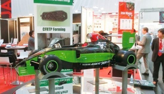
Asano, a Japanese metal-processing manufacturer serving the automotive and motorcycle industries, is clearly the second type of company, adopting 3D scanning technologies that have had an effect on its design and quality assurance processes.

A Business Mainstay

The company designs and manufactures a wide range of prototype sheet metal parts, metal moulds, jigs, machinery and other parts. The company also uses its technologies for projects such as reducing automotive weight through the use of carbon fibre-reinforced thermo-plastics.

Norimichi Abe, group leader of Asano’s general control group for CAD machine processing, began experimenting with 3D capture devices and software nearly 10 years ago. Mr Abe now considers reverse engineering a mainstay of the company’s business. He estimates that the company has completed more than 200 projects using such methods.

Such 3D capture devices typically use software such as 3D System’s Geomagic Design X to convert 3D scan data into high-quality feature-based CAD models. It is able to capture geometry for objects of all sizes and create manufacturing-ready designs, including automatic and guided solid model extraction, exact surface fitting to organic 3D scans, mesh editing and point cloud processing.

Mr Abe said that the reverse engineering software provides numerous features such as the ability to handle large point clouds, and a variety of modelling methods such as automatic surface creation.

Integrating Design For Greater Stability

A recent project for Spoon Inc, a Japanese company that provides tuning kits and specialised parts for Honda racing and street cars, called for Asano’s use of 3D scanning technologies.

The project involved designing a new plate for the front underbody of a Honda S660 sports car. The original part suffered from torsion during hard braking and rolling. The plate was designed originally as part of the complex base assembly of the car, which would have made it very time-consuming to redesign from scratch.

Instead of going back to the drawing board, Asano scanned the front underbody surface of the S660. The software was then used to process the scan data and design a new precision plate that could be mounted in place of the original.

“The redesigned plate could be attached to the car simply, without any processing, and it was so precise that the undercover could be mounted without alterations,” added Mr Abe.

The redesigned plate provided greater stability, according to Mr Abe, based on the fact that the suspension and body were integrated into a single box like a sub-frame.

Right The First Time

Beyond point capture and processing, the software can also be used by the quality assurance section to reduce the number of trial sheets for its prototypes and to produce an accurate mould on the first attempt.

“We are aggressively pursuing various new testing methods that are faster and more precise than the ones we have used in the past,” says Hiroshi Imai, section chief for quality assurance at Asano’s Gunma plant.

The software enables manufacturers to take measurements of parts from 3D scanners and compare them to digital reference data for first-article inspection and other metrology applications. The software subsequently generates 3D reports of measurements, tolerances and deviations.

Asano uses 3D scanning and the software to speed the parts testing process and gain more accurate data on deviations from the original design.

“During trial production, it is important to grasp the entire shape and surfaces of sheet metal parts,” said Tetsuya Matsumoto, who is in charge of testing the Asano quality assurance section. “Before we began using the software, if the results were not good enough when we pressed the prototypes and measured them with a laser, it was difficult to determine whether it was a problem with the shape or with the laser. This wasted a considerable amount of time.”

Two To Three Times Faster

Because of the time and effort required for capturing and processing the required data, Asano could only do product feature testing for mass-produced products.

“Except for the mass-produced products, the only testing methods available to us were to check the surface by 3D measurement to designate and measure arbitrary points on the surface,” said Mr Matsumoto.

This made it difficult to grasp the entire shape, and both time and labour were spent on clarifying product features. With a 3D scanning device and supporting software, Mr Matsumoto said that they could grasp the cause of deviations at a much faster rate.

“Our testing is two to three times faster than in the past, and we can aim for much higher manufacturing efficiency,” he added.

Adopting new technologies such as reverse engineering and 3D metrology is an ongoing process at Asano. “We anticipate needs and take up any and every challenge,” says said Akio Kishi, director of Asano’s management promotion office. “This stance is one of our company’s core strengths.”

Completed parts manufactured from 3D CAD data used with 3D scanning

Completed parts manufactured from 3D CAD data used with 3D scanning.

3D scan of car exterior

3D scan of car exterior.

Initial scan using software

Initial scan using software.

Modelling the chassis parts

Modelling the chassis parts.

CHECK OUT THESE OTHER ARTICLES
Creaform Moves Offices In Singapore
Kennametal Launches 3D Printing Business Unit
Faro Launches Cobalt Design Structured Light 3D Scanner
GEFERTEC At EMO: New-Generation Machines And Applications For 3D Metal Printing
Achieving Perfect Gaps And Joints
ZEISS Completes GOM Acquisition
Hexagon Launches QUINDOS 2019.2
Getting Ahead in the Medical Market
Blum-Novotest To Highlight Measuring, Testing Technology at EMO 2019
Hexagon Production Software Portfolio Merges Virtual and Real Manufacturing at EMO 2019
WANT MORE INSIDER NEWS? SUBSCRIBE TO OUR DIGITAL MAGAZINE NOW!

FOLLOW US ON: LinkedIn, Facebook, Twitter


MaxShot Next

MaxShot Next

MaxShot Next by Creaform is an optical coordinate measuring system for large-scale metrology projects, is designed for use by quality control and product development specialists from the aerospace, automotive and transportation industries.

The system features live go/no-go guidance feature for accurate and reliable measurements for their large-scale metrology projects.

The MaxShot 3D photogrammetry cameras can be used as a standalone measurement device and also be used in combination with the company’s 3D scanners and portable CMMs. Features include volumetric accuracy of up to 0.015 mm/m, ergonomic design engineered specifically for photogrammetric measurement of large parts ranging from two to 10 metres, improved hardware reliability and multifunction buttons.

CHECK OUT THESE OTHER ARTICLES

Achieving Perfect Gaps And Joints
ANCA Motion’s Multi-Axis Servo System Conserves 96 Percent Of Energy Wastage
Airbus Opens Automated A320 Assembly Line
Hypertherm Releases Major Version Update Of Robotmaster Robot Programming Software
Walter Enables Automatic Detection and Alignment of Tools and Blanks
NIMS Partners With OMIC To Develop Metrology Standards And Certification
3D Goes Long-Range With The First Scanning Laser Tracker
Creaform Moves Offices In Singapore
Creaform Adds Academia 50 3D Scanner To Its Educational Solution Suite
Kennametal Launches 3D Printing Business Unit

WANT MORE INSIDER NEWS? SUBSCRIBE TO OUR DIGITAL MAGAZINE NOW!
FOLLOW US ON: LinkedIn, Facebook, Twitter


Hexagon: Leica T-Probe

Hexagon: Leica T-Probe

The Leica T-Probe from Hexagon is a measurement tool that is accurate to +/-35 µm and has a point rate output of 1,000 points per second and a tracking speed of >1 m/s.

The T-Probe has a feature which automatically re-establishes interrupted line of sight, allowing users to work freely without having to regularly stop and relocate the beam, resulting in less downtime.

The measurement tool comes in various T-Probe styli lengths and can gather data in hard-to-reach places without the need for direct line of sight. The T-Probe laser tracker can be set in a specific position to measure within a spherical volume of up to 40 m using the T-Probe, which helps to ensure accuracy, maintain data integrity and save time.

CHECK OUT THESE OTHER ARTICLES

Tungaloy Boosts Deep Hole Drilling Productivity
Collaborative Robot Market To Exceed US$11 Billion By 2030
One Technology—Many Benefits
Hexagon Launches PC-DMIS 2019 R2
Heimatec To Showcase New Products, Tool Innovations At EMO 2019
Tungaloy’s New NDL Geometry Makes Deep Holes Easier To Drill
Hypertherm Releases Major Version Update Of Robotmaster Robot Programming Software
A Look at Walter’s Two-in-One Machining Concept
High Speed Accurate Machining
EMO 2019: Mobile Hybrid Machining For The Tool And Die Industry

WANT MORE INSIDER NEWS? SUBSCRIBE TO OUR DIGITAL MAGAZINE NOW!

FOLLOW US ON: LinkedIn, Facebook, Twitter


Back To Top